Drives such as voice coil, linear, or torque motors are electromagnetic direct drives. In direct drives, the force of the drive element is transmitted directly to the load to be moved (e.g., to a linear or rotary table, without mechanical transmission elements such as coupling, drive screw, or gearhead). Electromagnetic direct drives consist of a winding body (coil) in which a magnetic field is formed when current runs through it and a carrier or magnet assembly on which the magnets are mounted.
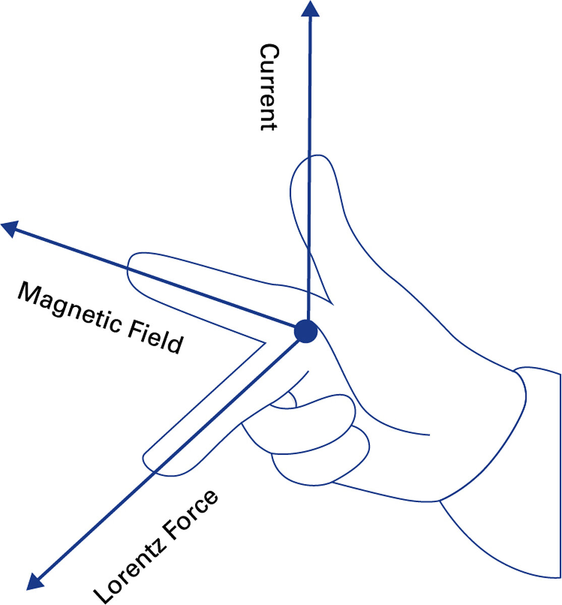
The force or torque for the acceleration of the load is generated by the Lorentz force. This force is proportional to the magnetic field strength and the current passing through the current-carrying conductor. The electrical energy is converted here into mechanical energy. The generated force acts bidirectionally depending on the direction of the current. In principle, either the winding body (“moving coil”) or the magnet assembly (“moving magnet”) can be moved. The moving part is referred to as the secondary part, the static part as the primary part.
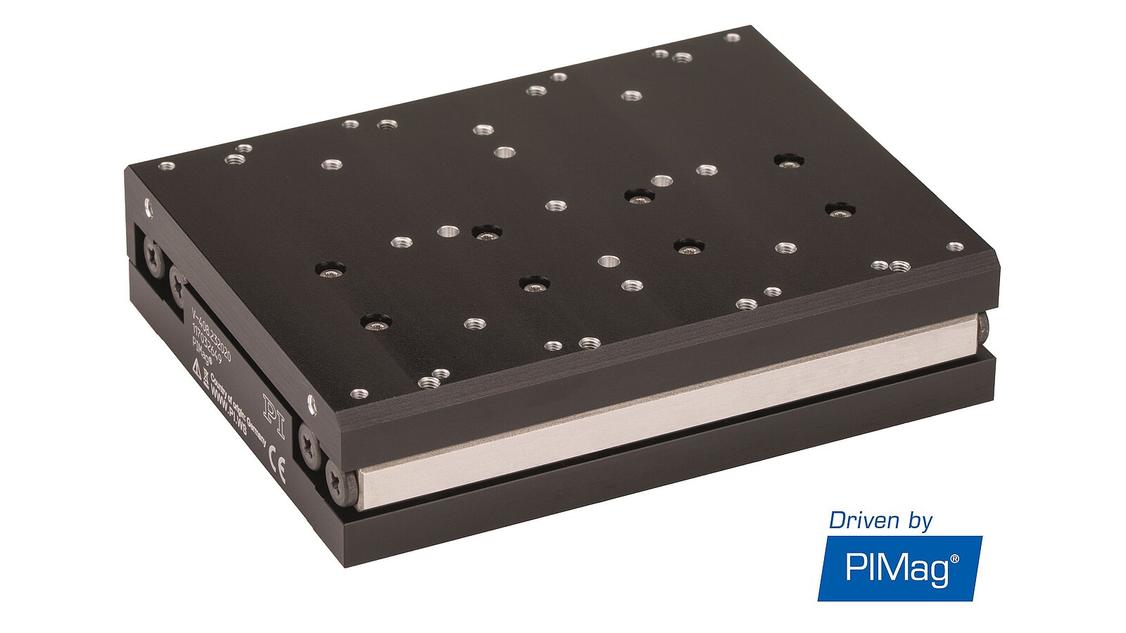
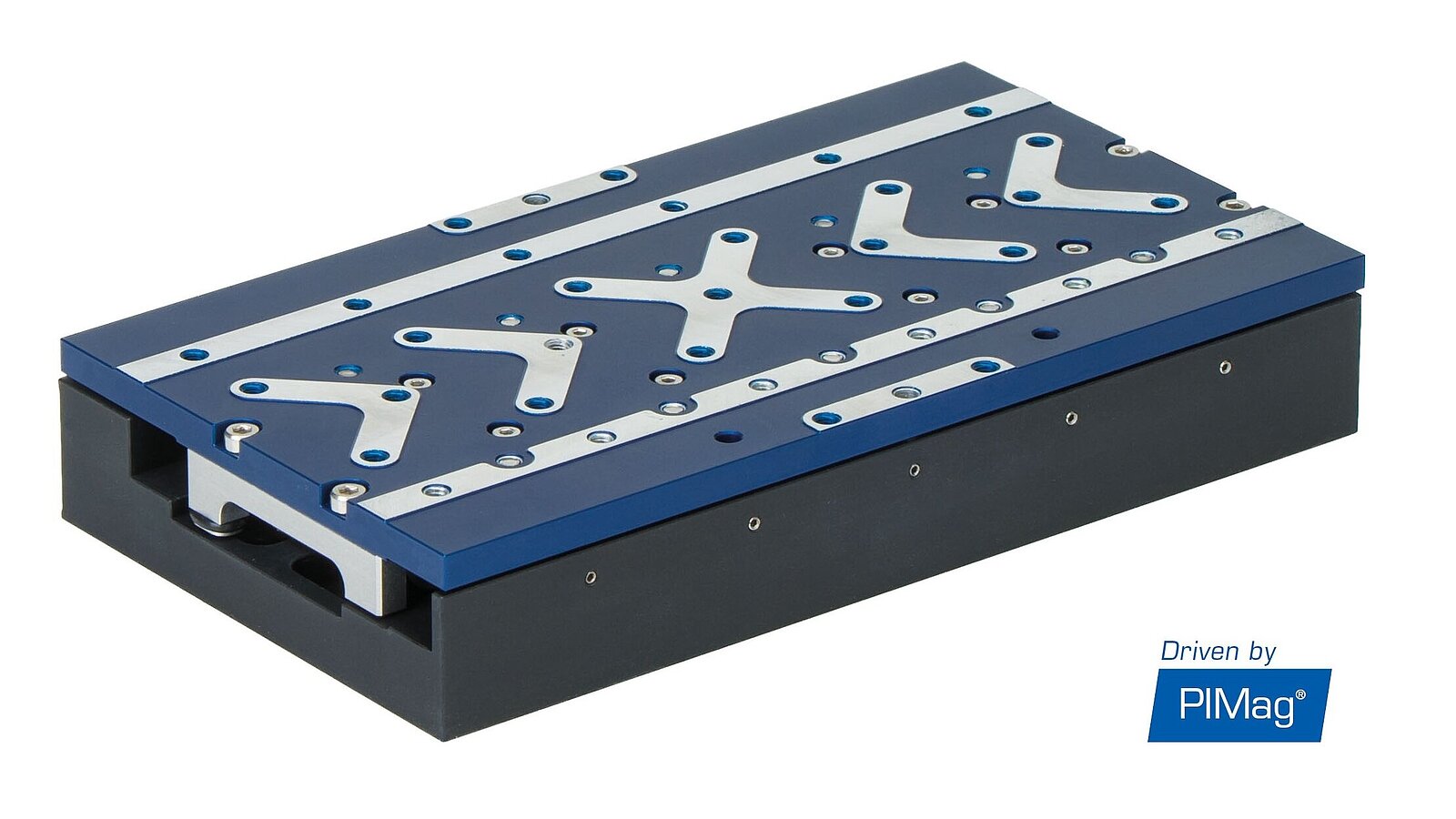
PI has many standard and customer-specific positioning solutions on offer that are equipped with magnetic direct drives; the company has also many years of experience in the design, construction, and manufacture of the necessary system components such as guides, sensors, control technology, and software. PI can also develop proprietary magnetic motors if positioning systems need to achieve specific performance characteristics that cannot be reached by using drive components currently available on the market, for example, to achieve a high force density or a compact design. These proprietary motors, developed in-house, are identified by the PIMag® brand name and positioning systems using these PI motors are identified by the Driven by PIMag® logo.
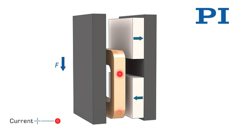
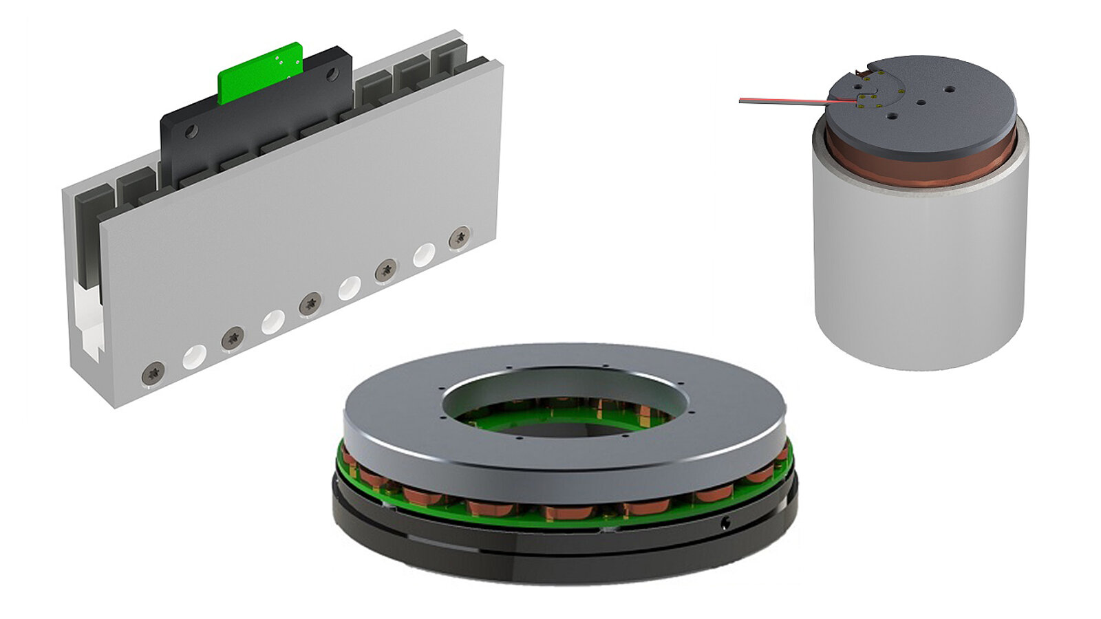
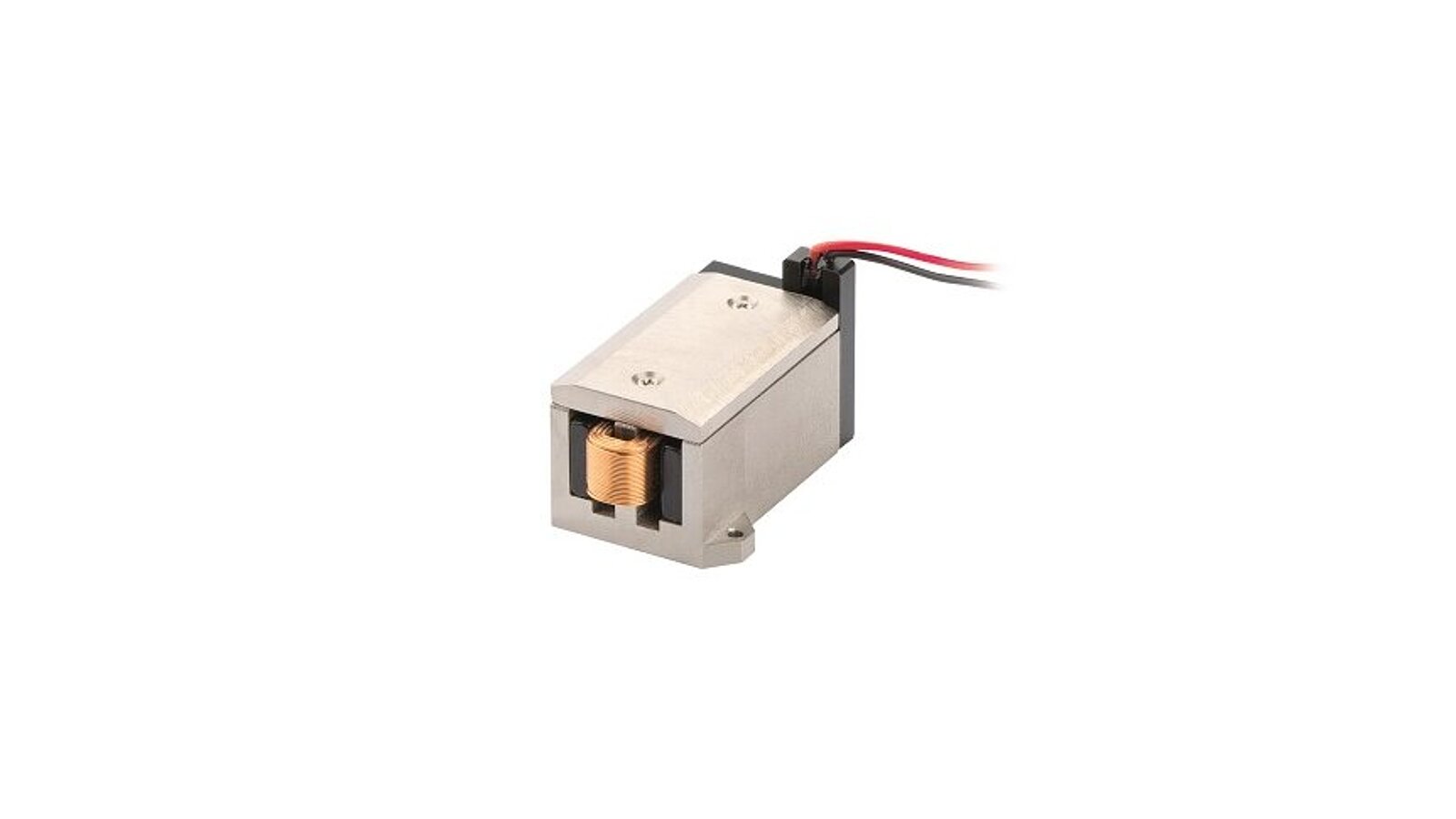
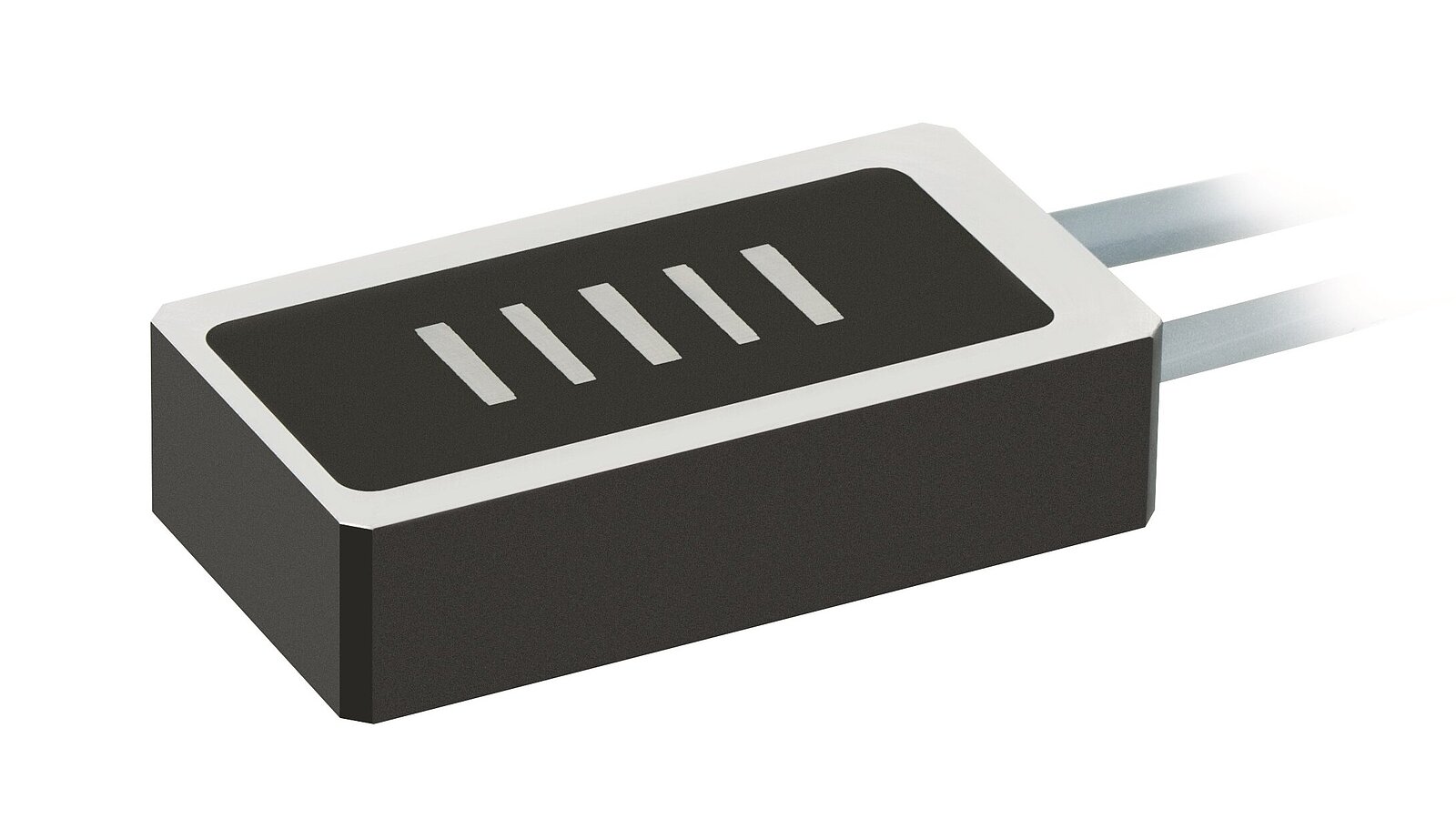
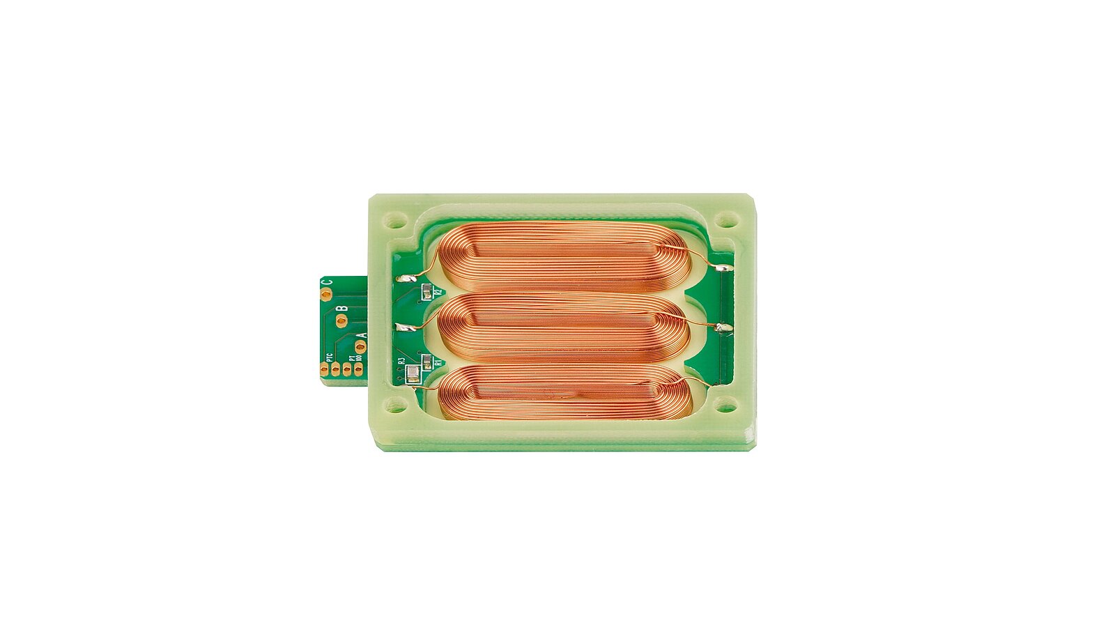
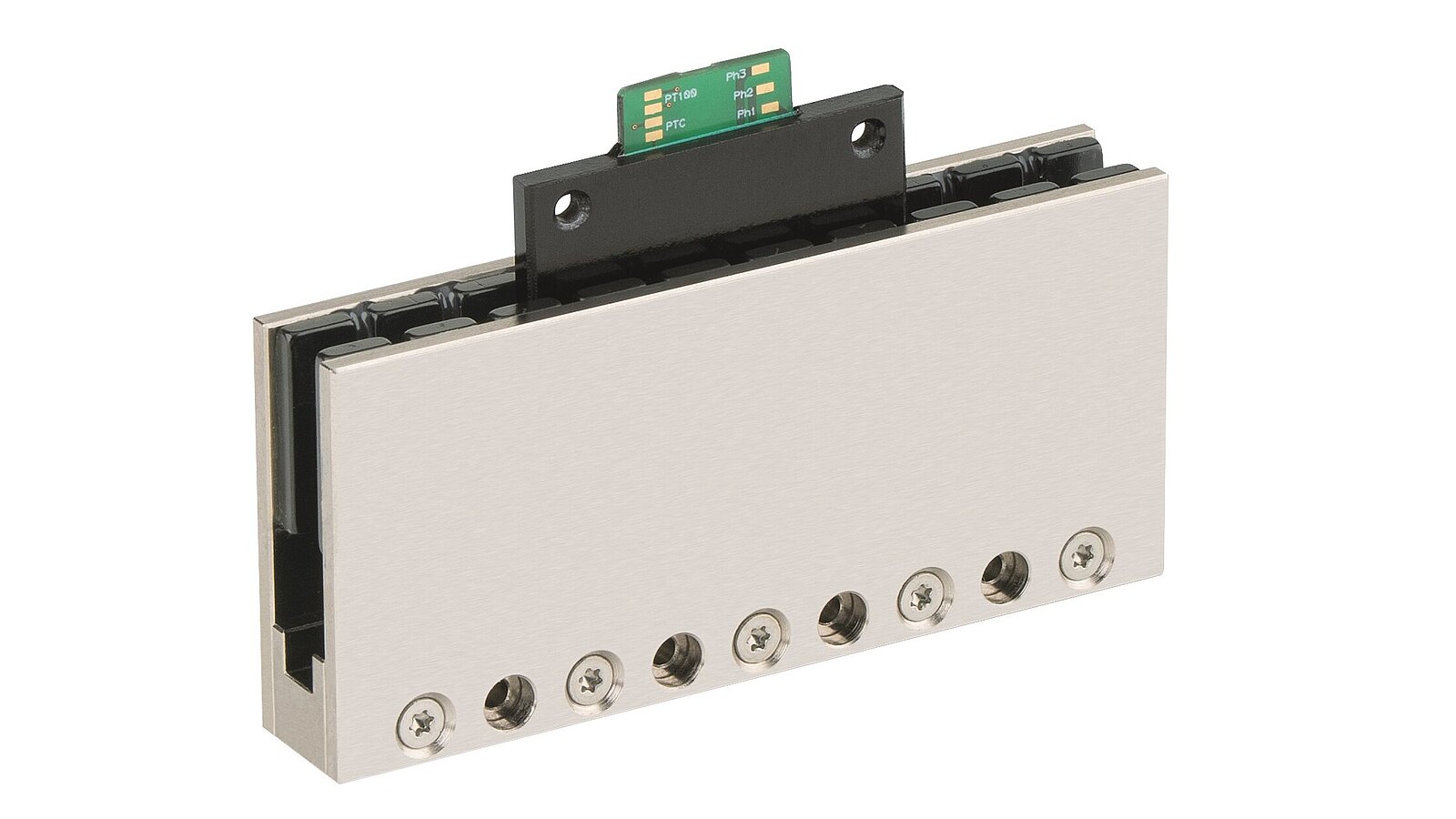
Voice coil drives are single phase motors consisting of a permanent magnet and a winding body that are located in the air gap of the magnetic field. When current flows through the winding body, it moves in the magnetic field of the permanent magnet. Particularly compact dimensions can be achieved when rectangular or flat shapes are built.
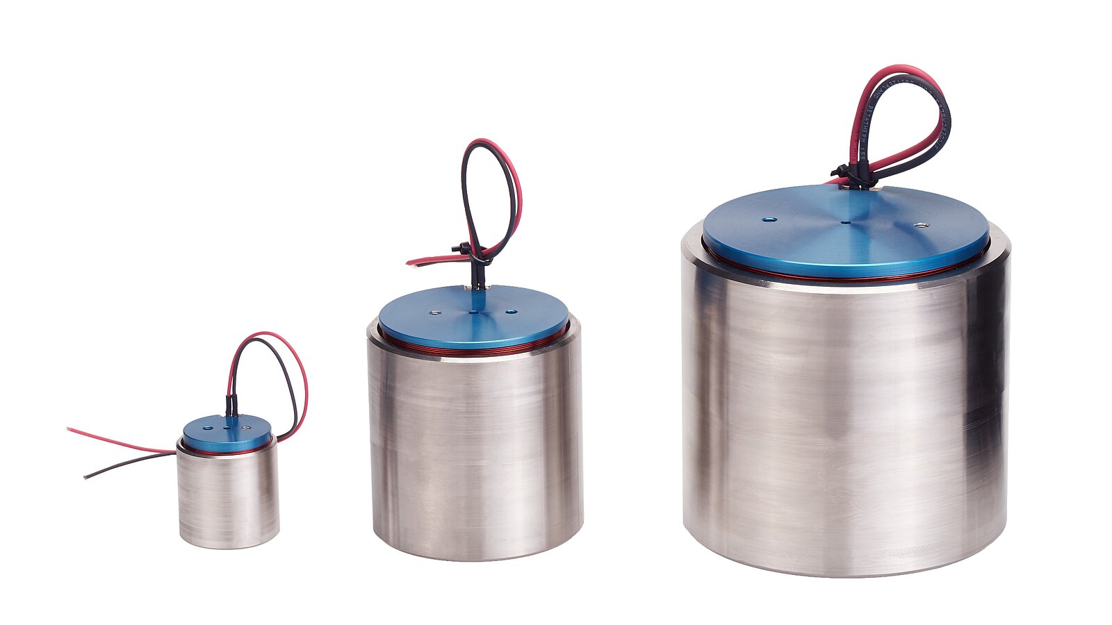
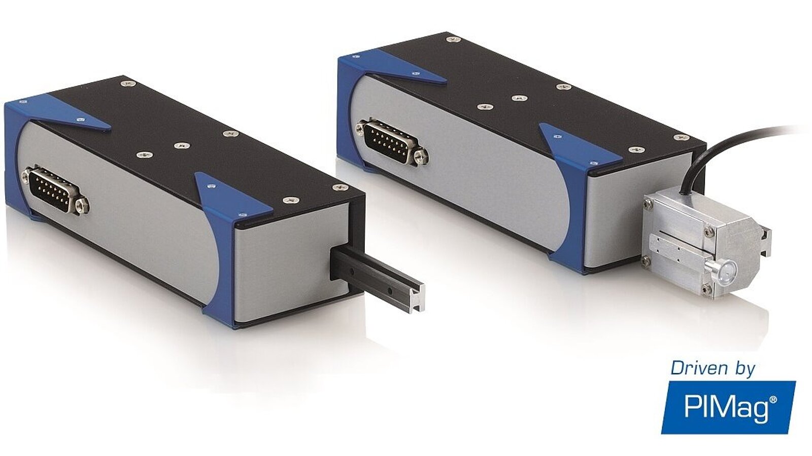
Cylindrical voice coils are constructed according to the plunger coil principle (i.e., the coil sits in a field assembly). Either the winding body or the field assembly can be moved. With the so-called multi-coil principle, the motor constant of cylindrical voice coil motors can be optimized in compact installation spaces and even solutions with hollow shafts can be realized, for example. Voice coil drives are suitable for scanning applications that require high precision, high dynamics, and high velocities at travel ranges up to ten millimeters.
Voice coils can also be optimized for force or motor constant. The motor constant denotes the ratio of force to power loss. The higher the motor constant, the less heat is produced when a certain force is generated. It describes the efficiency of the motor in regard to converting electrical into kinetic energy. As the temperature rises, the winding resistance and, therefore, also the power loss increase, which is why the motor constant is temperature-dependent.
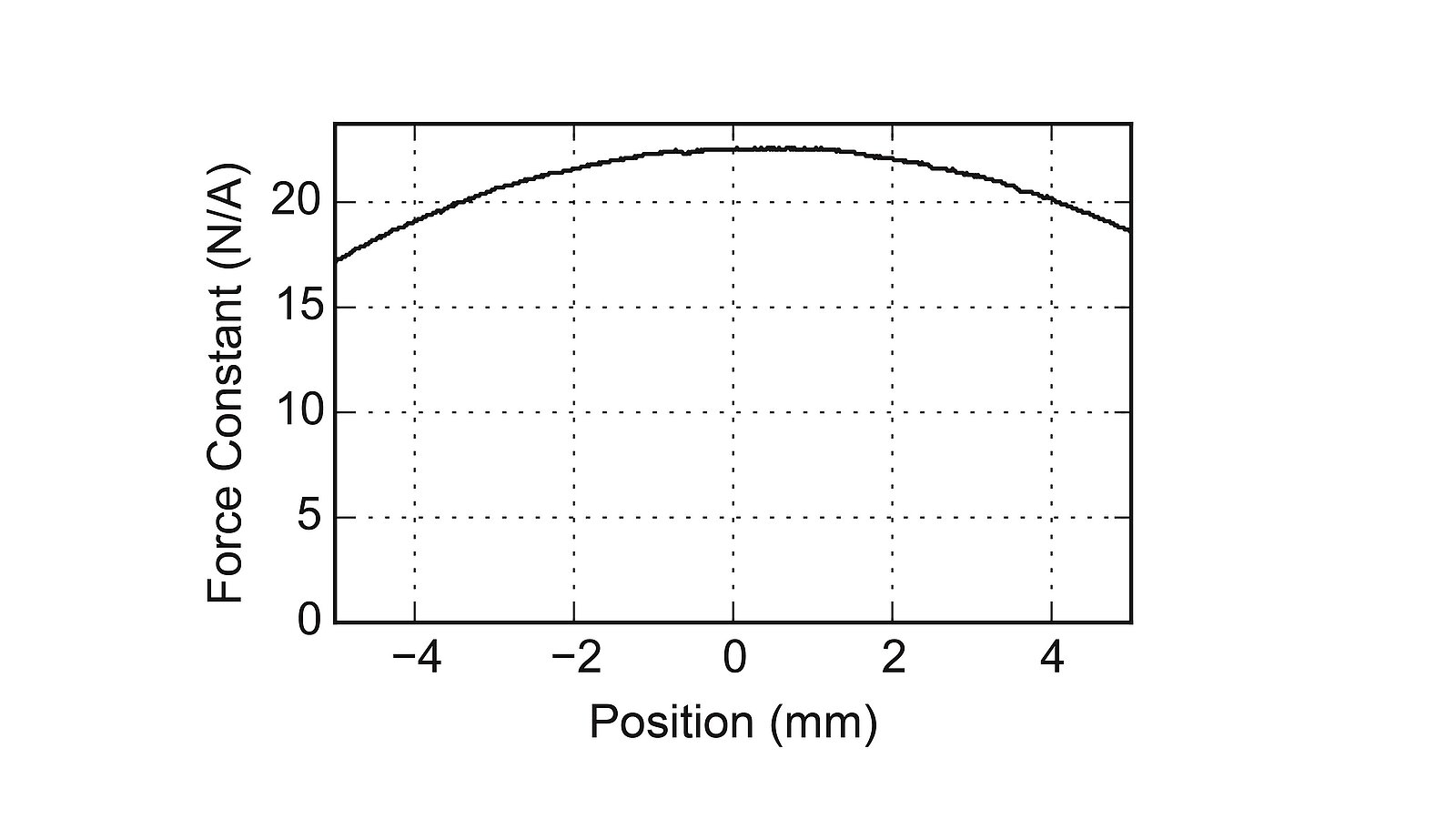
The force depends on the position since the coils move in relation to the permanent magnets along the travel range. In order to drive the force into the motor as quickly as possible, the voltage can be increased since the current is then made available correspondingly faster. The acceleration increases in the same ratio. Highly dynamic applications are, therefore, possible through a fast increase in acceleration (jerk). Cylindrical motors are used, for example, in positioning solutions for focusing tasks in order to dynamically move a measuring head or an optical system vertically, or in endoscopes.
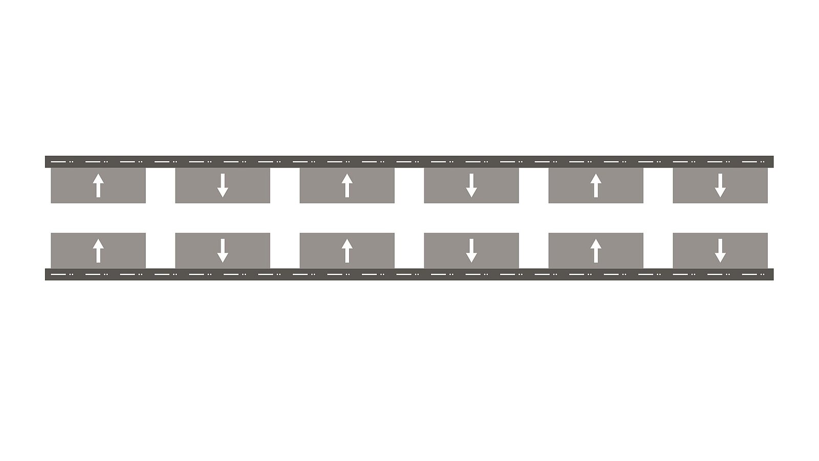
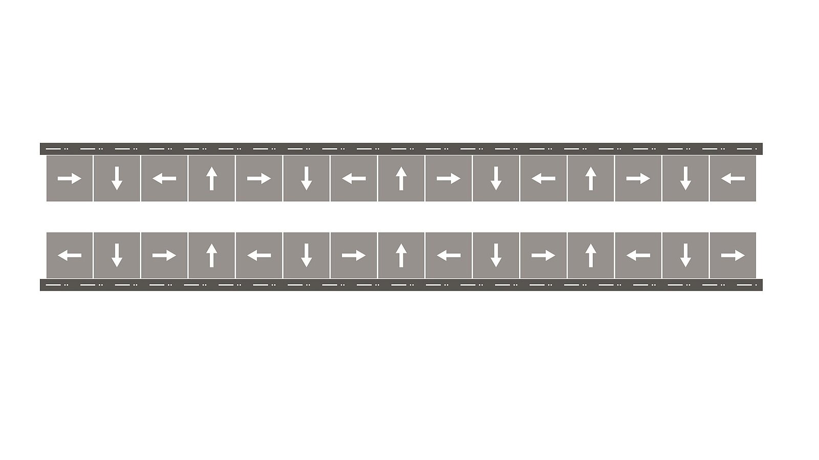
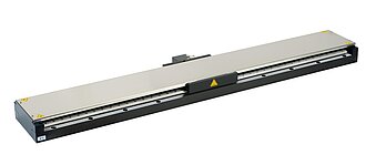
Linear Motors
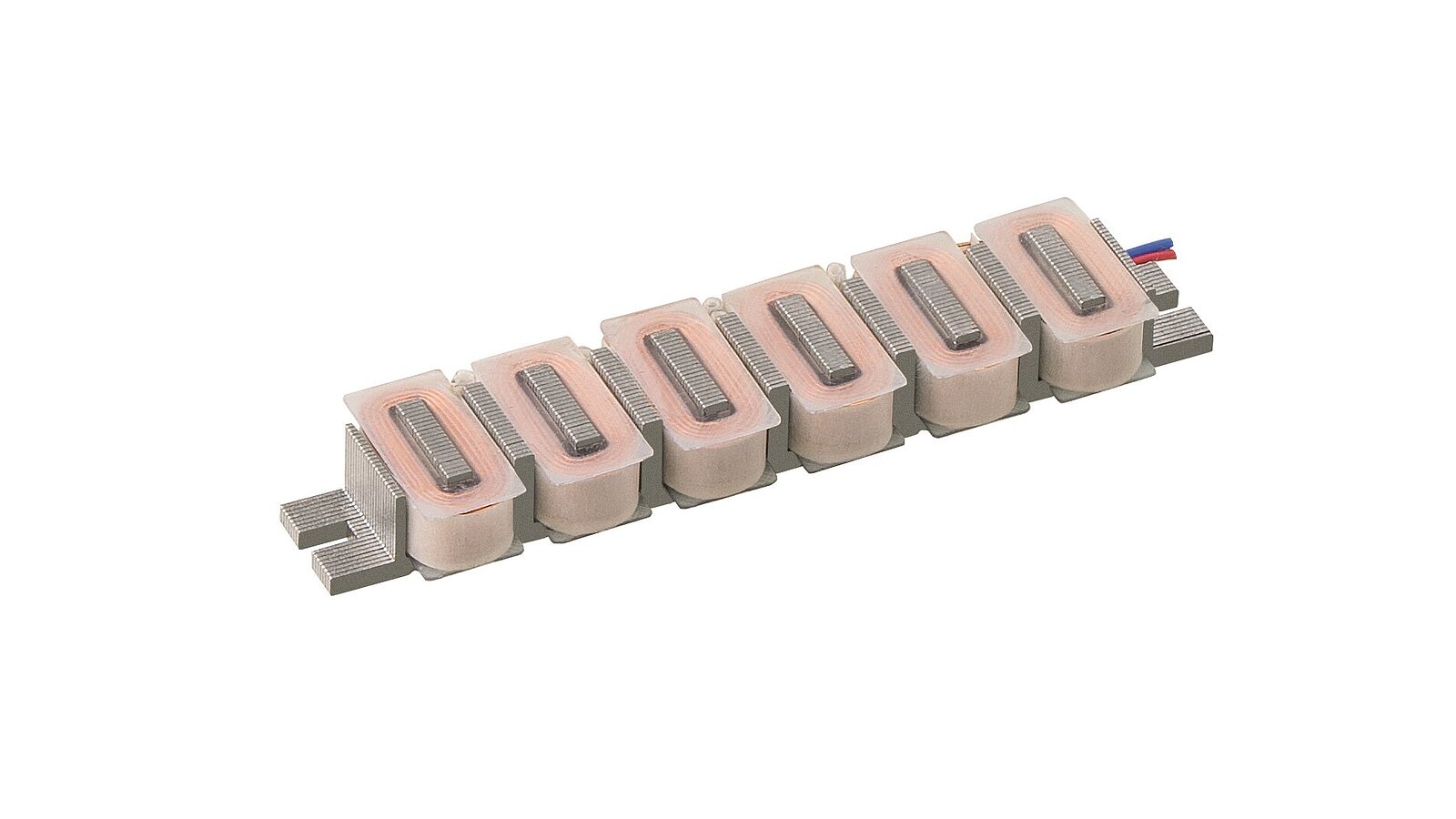
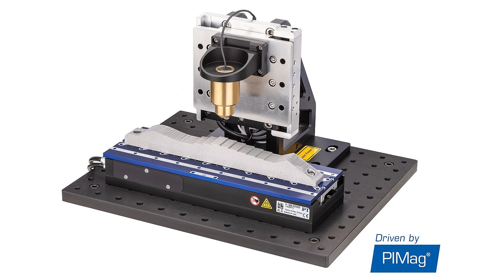
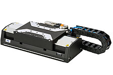
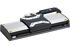
A classical 3-phase linear motor is basically a series of at least three (or a multiple of three) voice coil motors. The individual coils can be controlled according to a position-dependent, fixed pattern (i.e., commutated). Linear motors are used both for very high and for very low feed velocities. They work precisely in a range from below 0.1 µm/s to more than 5 m/s. If combined with air or magnetic bearings, a position resolution down to a few nanometers is possible.
Optionally, under vacuum, PI can apply a special epoxy resin to its linear motors. This results in an improved heat dissipation, whereby higher nominal forces can be achieved. In addition, the sealing compound ensures that the motor is encapsulated and therefore protected against external damage (e.g., during assembly). For applications that require high velocities or fast current rise times, PI can design motors for very high operating voltages of up to 600 VDC.

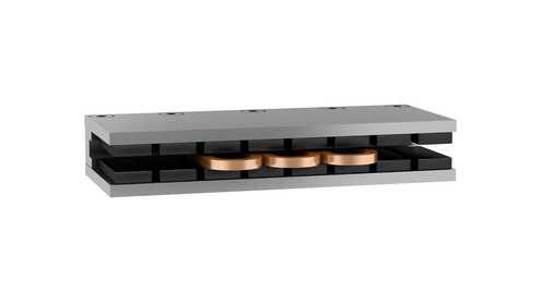
The magnetic tracks used in PI linear motors are available in various lengths, they can be connected in series in order to realize any desired travel range. Single-sided or U-shaped magnetic tracks are available.
U-shaped magnetic tracks achieve higher magnetic field strengths and thus higher forces than single-sided magnetic tracks. If the magnets are additionally arranged as a Halbach array, the magnetic field strength can be increased by about 10% compared to a North Pole to South Pole arrangement. In addition, the iron counterplate can be omitted in a Halbach array, making these magnetic tracks significantly lighter. The advantages of using a Halbach array also apply to single-sided magnetic tracks. In this case, the use of Halbach arrays minimizes stray fields on the rear side. PI offers carbon supports for applications that require ultra-light magnetic tracks.
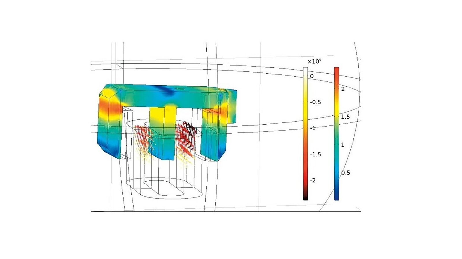
In iron-core motors, the core of the coil unit consists of iron. The iron maximizes the magnetic forces and contributes to a high force density and a high thermal stability. To reduce eddy current losses, the iron is laminated and it is mostly made of stacked and insulated transformer plates.
The iron in the coil unit causes attraction forces between the coil unit and the magnet assembly, leading to the occurrence of cogging and therefore to a fluctuation of the feed force over the travel range. Specially designed marginal teeth optimize the cogging. Iron-core linear motors are suitable for applications requiring high forces and accelerations while having a limited installation space.
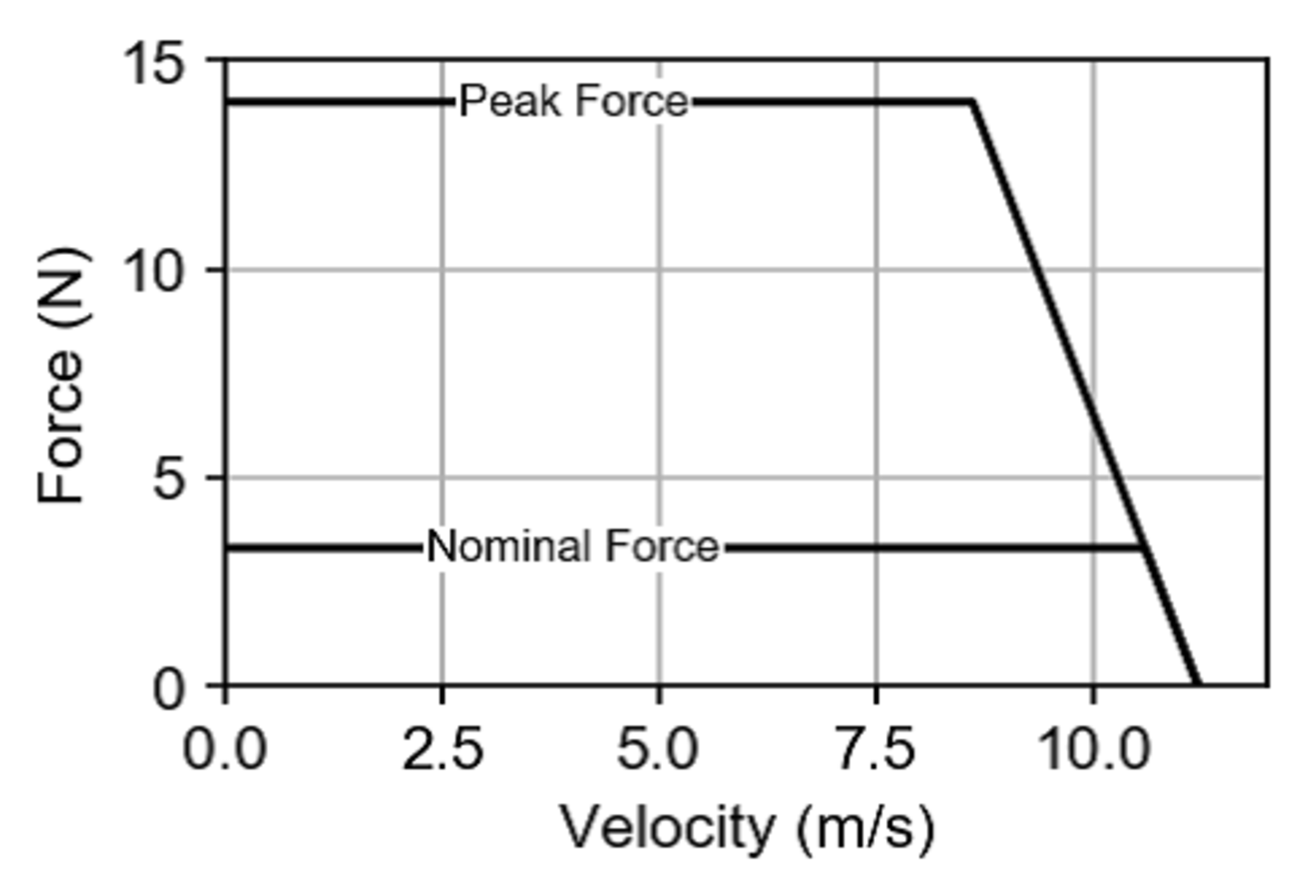
The winding body of ironless linear motors does not have an iron core. This means that there are no attracting forces between the coil and the magnet assembly and cogging does not occur. The lack of an iron core also reduces the weight of the motor itself. Since there is no cogging that affects the guides and feed velocity, and the winding body is lighter, ironless motors are characterized by high travel accuracy, high velocity stability, and high accelerations. Power and dynamics requirements can be met by increasing the number or the dimension of the motor coils. In most cases, ironless motors achieve lower nominal and peak forces than iron-core motors. This is due to the lack of thermally conductive metals in the design and the resulting limited heat dissipation from the coils. The motors are, therefore, protected against overload by means of temperature sensors.
Ironless linear motors are suitable for applications requiring high dynamics in a compact installation space, while having the highest demands on precision.
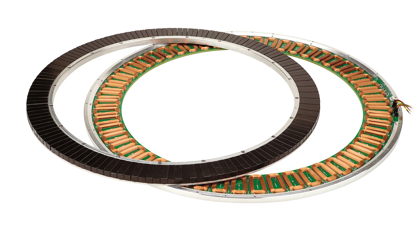
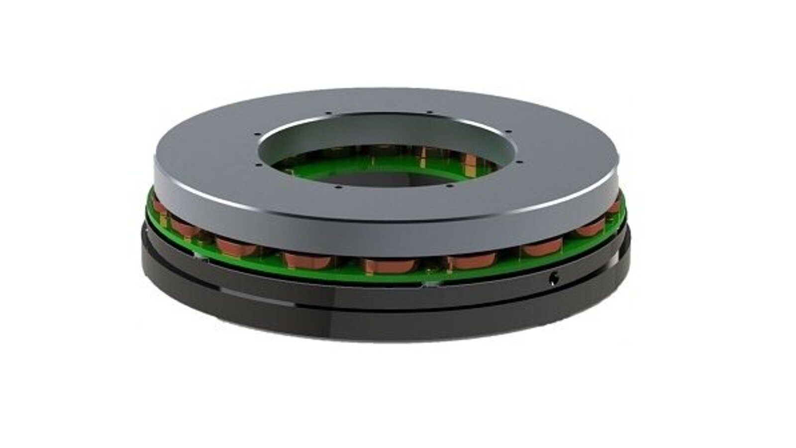
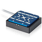
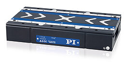
In principle, a torque motor is a linear motor that is arranged radially. The stator of the torque motor contains coils and is firmly mounted; the rotor contains the magnet assembly. While the magnet length scales linearly, the torque scales quadratically with the diameter. Therefore, large torques are generated on a large diameter. In addition, large radial dimensions make it possible to create apertures for the passage of laser beams or cables.
Because of the direct drive principle, torque motors are backlash free. The zero-play allows high positioning accuracy and high drive rigidity, resulting in high repeatability. The high drive torque enables high acceleration and therefore high dynamics. Additional features include high torsional rigidity, high peak torques, high degrees of efficiency, as well as very smooth running.
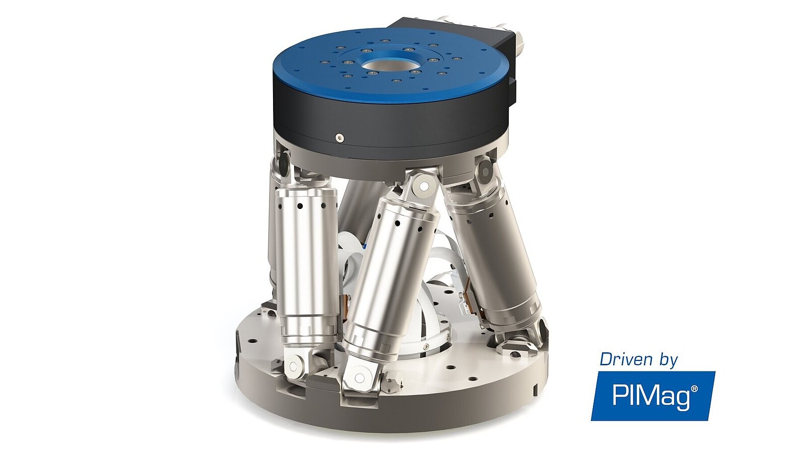
Among others, torque motors are suitable for high load rotation stages on single or multi-axis assemblies thanks to their compact design with respect to torque and rotational symmetry.
Position, Velocity, and Force Control
Because they are current-controlled, with the driving force being linearly dependent on the current, magnetic direct drives cannot only be operated based on position or velocity control, but also force control.
The force control allows operation with a defined holding or feed force. The force and position sensors can be read individually or simultaneously in a double control loop. In addition to pure force control, subordinate position and velocity control is also an option. The auto-zero function defines the holding current at which the drive produces a force of 0 N during open-loop operation.
Weight Force Compensation
Magnetic direct drives installed vertically must hold both the motion platform and the load of the application against gravity. This is possible thanks to weight force compensation. It is adapted to the load and keeps the components to be moved in position even without motor forces. This allows the motor force to be used exclusively for the positioning task. The weight force can be compensated magnetically, pneumatically, or mechanically. PI uses different methods depending on the required performance characteristics.


Downloads
PIMag®: Voice Coil, Linear, and Torque Motors Developed In-house
Individual design of magnetic direct drives for flexible, competitive, and application-specific positioning solutions
Rotating Electric Motors for Precision Positioning
An application-related comparison of different motor types